 Firing
order 1-3-4-2
Firing
order 1-3-4-2|
Automotive Torque Specifications |
||
| Home | Mazda | Mazda Pick-Ups 1972-93 |
Mazda Pick-Ups 1972-93
Engine
| B2600 (2.6L) Engine (1988 and Earlier) | ||||
|---|---|---|---|---|
| Components | Torque | |||
| balance shaft chain guide bolts | left guide (A) and upper guide (B) | 3.6-5.8 ft. lbs. | ||
| lower guide | upper bolt | 5.8-6.5 ft. lbs. | ||
| lower bolt | 11-15 ft. lbs. | |||
| balance shaft drive gear | 22-29 ft. lbs. | |||
| balance shaft sprocket bolt | 43-50 ft. lbs. | |||
| balance shaft thrust plate bolts | 7.3-7.9 ft. lbs. | |||
| camshaft bearing cap bolts | all except cap #5 | 14-15 ft. lbs. | ||
| cap #5 | 15-20 ft. lbs. | |||
| camshaft sprocket bolt | 8.7-10.2 ft. lbs. | |||
| crankshaft sprocket/Pulley bolt | 80-94 ft. lbs. | |||
| cylinder head bolts | cold (Initial) | 65-72 ft. lbs. | ||
| warm (Final) | 72-79 ft. lbs. | |||
| cylinder head-to-Timing chain cover bolts | 11-16 ft. lbs. | |||
| distributor drive gear nut | 8.7-10.2 ft. lbs. | |||
| engine mount bracket | 36-43 ft. lbs. | |||
| exhaust manifold nuts | 11-14 ft. lbs. | |||
| flywheel bolts | 1972-88 | 94-101 ft. lbs. | ||
| 1989 and later | 67-72 ft. lbs. | |||
| intake manifold nuts | 11-14 ft. lbs. | |||
| jet valves | 13-15 ft. lbs. | |||
| main bearing cap bolts | 54-61 ft. lbs. | |||
| oil pan bolts | 4.3-5.1 ft. lbs. | |||
| oil pressure sending unit | 11-15 ft. lbs. | |||
| oil pump mounting bolt | 5.7-6.5 ft. lbs. | |||
| Oil pump sprocket bolt | 22-29 ft. lbs. | |||
| oil strainer bolts | 11-16 ft. lbs. | |||
| rear oil seal housing-to-Block bolts | 7.3-8.7 ft. lbs. | |||
| rocker arm cover bolts | 3.6-5.1 ft. lbs. | |||
| rod bearing cap nuts | 33-35 ft. lbs. | |||
| thermostat housing-to-Engine bolts/Nuts | 6mm Bolts/Nuts | 5-7 ft. lbs. | ||
| 8mm Bolts/Nuts | 12-17 ft. lbs. | |||
| timing chain cover bolts | 8.7-10.2 ft. lbs. | |||
| timing chain guide bolts | 7.2-8.7 ft. lbs. | |||
| water pump bolts | 104-122 in. lbs. | |||
|
|
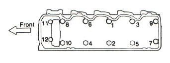
| Fig. 1 | Cylinder Head Bolt Torque Sequence. |
|
|
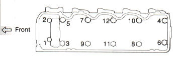
| Fig. 2 | Cylinder Head Bolt Loosening Sequence. |
|
|
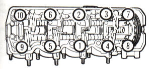
| Fig. 3 | Camshaft Bearing Cap Bolt Torque Sequence. |
|
|
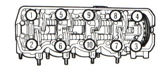
| Fig. 4 | Camshaft Bearing Cap Loosening Sequence. |
|
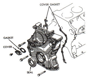
|
| Fig. 5 | Timing Chain Cover Components. |
|
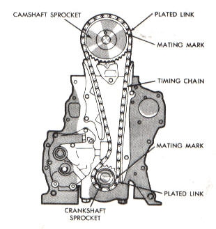
|
| Fig. 6 | Camshaft And Crankshaft Timing Mark Alignment. |
|
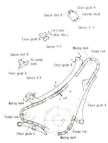
|
| Fig. 7 | Balance Shaft Timing Mark Alignment. |
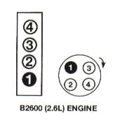
| Firing
order 1-3-4-2 |
|
| Fig. 8 | Cylinder Location And Firing Order. |
![]()
For images, go to www.torquespecs.com
|
|