|
|
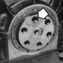
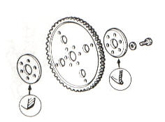
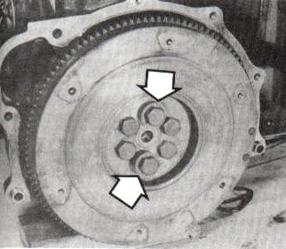 If
your flywheel has washers on some bolts, you may have a flywheel with a
special bolt. See the following pictures. If
your flywheel has washers on some bolts, you may have a flywheel with a
special bolt. See the following pictures. |
| Fig. 1 |
Flywheels With Odd Bolt. |
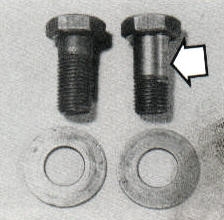 The
bolt on the left is the normal bolt. The bolt on the right is the special
bolt. There is only one of the bolts on the right. The
bolt on the left is the normal bolt. The bolt on the right is the special
bolt. There is only one of the bolts on the right. |
| Fig. 2 |
Flywheel Bolts. |
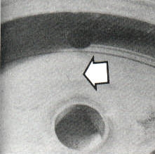 Look
for the mark on the flywheel next to the bolt hole for the special bolt.
You will need this to align the flywheel with the crankshaft, when you
reinstall the flywheel. Look
for the mark on the flywheel next to the bolt hole for the special bolt.
You will need this to align the flywheel with the crankshaft, when you
reinstall the flywheel. |
| Fig. 3 |
Mark On The Flywheel Next To The Special Bolt Bolt Hole. |
 Line
up the hole in the crankshaft, with the mark next to it for the special
bolt, with the stepped hole in the crankshaft. This is the way you align
the flywheel with the crankshaft. Line
up the hole in the crankshaft, with the mark next to it for the special
bolt, with the stepped hole in the crankshaft. This is the way you align
the flywheel with the crankshaft. |
| Fig. 4 |
Stepped Hole In The Crankshaft For The Special Bolt. |
 |
| Fig. 5 |
Automatic Driveplate (Flywheel). |
 Click
for larger picture. Click
for larger picture. |
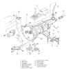
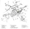
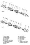
| Fig. 6 |
Typical Manual Transmission Components (2WD) |
 Click
for larger picture. Click
for larger picture. |
| Fig. 7 |
Typical Manual Transmission (4WD). |
 Click
for larger picture. Click
for larger picture. |
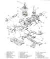
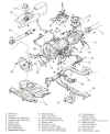
| Fig. 8 |
Typical Clutch Components. |
 Click
for larger picture. Click
for larger picture. |
| Fig. 9 |
Typical Automatic Transmission (2WD). |
 Click
for larger picture. Click
for larger picture. |
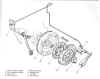
| Fig. 10 |
Typical Automatic Transmission (4WD). |
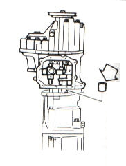 When
removing the transfer case from the transmission, be careful not to drop
the input sleeve. (Arrow) When
removing the transfer case from the transmission, be careful not to drop
the input sleeve. (Arrow) |
| Fig. 11 |
Transfer Case. |
 Click
for larger picture. Click
for larger picture. |
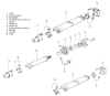
| Fig. 12 |
One And Two Piece Driveshaft Assemblies. |
 Click
for larger picture. Click
for larger picture. |
| Fig. 13 |
4WD Driveshaft Assemblies. |
 Click
for larger picture.
Click
for larger picture.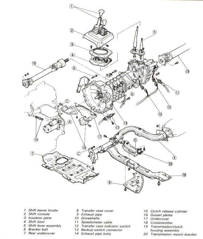 Click
for larger picture.
Click
for larger picture.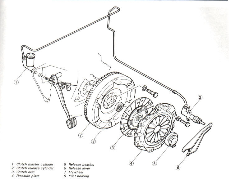 Click
for larger picture.
Click
for larger picture.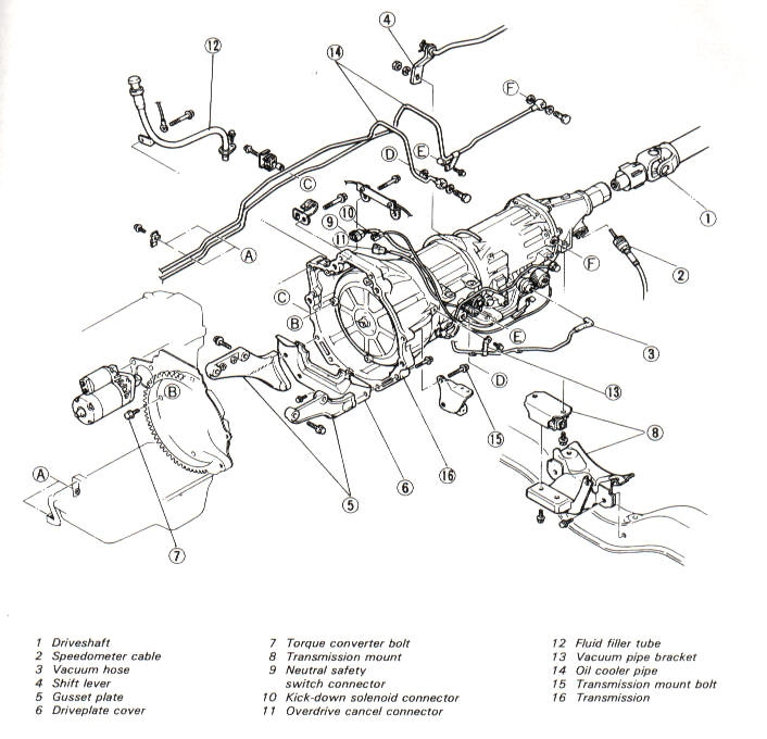 Click
for larger picture.
Click
for larger picture.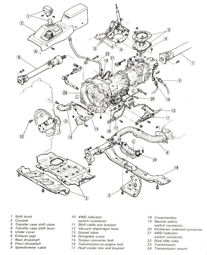 Click
for larger picture.
Click
for larger picture. Click
for larger picture.
Click
for larger picture. Click
for larger picture.
Click
for larger picture.