|
|
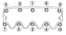 |
| Fig. 1 |
Cylinder Head Bolt Torque Sequence 1982-88 |
 |
| Fig. 2 |
Cylinder Head Bolt Torque Sequence 1989-90 |
 |
| Fig. 3 |
Cylinder Head Bolt Torque Sequence 1991-94 GA16DE 1.6L DOHC Engine. |
 |
| Fig. 4 |
Cylinder Head Bolt Torque Sequence 1991-94 SR20DE 2.0L DOHC Engine. |
 |
| Fig. 5 |
Camshaft Bearing Cap Torque Sequence GA16DE 1.6L DOHC Engine. |
 |
| Fig. 6 |
Camshaft Bearing Cap Loosening Sequence GA16DE 1.6L DOHC Engine. |
 |
| Fig. 7 |
Camshaft Bearing Cap Torque Sequence SR20DE 2.0L DOHC Engine. |
 |
| Fig. 8 |
Camshaft Bearing Cap Loosening Sequence SR20DE 2.0L DOHC Engine. |
 |
| Fig. 9 |
Timing Gear Alignment (With Timing Belt) |
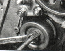 To
adjust timing belt tension, use flat blade screw driver. Insert screw
diver into slot and turn counter-clockwise, until slack is taken up in the
timing belt. Then tighten the center bolt. To
adjust timing belt tension, use flat blade screw driver. Insert screw
diver into slot and turn counter-clockwise, until slack is taken up in the
timing belt. Then tighten the center bolt. |
| Fig. 10 |
Timing Belt Tensioner. |
 |
| Fig. 11 |
Timing Gear Alignment 1989-90 (With Timing Chain). |
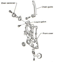 |
| Fig. 12 |
Typical Timing Chain Cover. |
 |
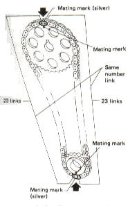
| Fig. 13 |
Timing Chain Alignment GA16DE 1.6L DOHC Engine. |
 |
| Fig. 14 |
Upper Timing Chain Alignment SR20DE 2.0L DOHC Engine. |
 |
| Fig. 15 |
Timing Chain-to-Crankshaft Alignment SR20DE 2.0L DOHC Engine. |
 The
timing chain tensioner must be fully retracted before installation. It
must be installed with the cast-in arrow pointing towards the front of the
engine. The
timing chain tensioner must be fully retracted before installation. It
must be installed with the cast-in arrow pointing towards the front of the
engine. |
| Fig. 16 |
Timing Chain Tensioner. |
 This
oil pump is located under the oil filter. This
oil pump is located under the oil filter. |
| Fig. 17 |
Oil Pump 1982-88 (With Timing Belt). |
 This
oil pump is located inside the timing chain cover. This
oil pump is located inside the timing chain cover. |
| Fig. 18 |
Oil Pump 1989-94 (With Timing Chain). |
 |
| Fig. 19 |
Main Bearing Cap Torque Sequence. |
 After
removing all the bolts holding the aluminum section of the oil pan to the
block, remove the two bolts in the transmission (see picture), then
install them into the threaded holes in pan (see picture). Tightening
these bolts will separate the pan from the block. When finish, reinstall
the bolts to the transmission. After
removing all the bolts holding the aluminum section of the oil pan to the
block, remove the two bolts in the transmission (see picture), then
install them into the threaded holes in pan (see picture). Tightening
these bolts will separate the pan from the block. When finish, reinstall
the bolts to the transmission. |
| Fig. 20 |
SR20DE 2.0L DOHC Engine Oil Pan Removal. |
 Firing
order 1-3-4-2 Firing
order 1-3-4-2 |
| Fig. 21 |
Cylinder Location And Firing Order 1990 And Earlier. |
 Firing
order 1-3-4-2 Firing
order 1-3-4-2 |
| Fig. 22 |
Cylinder Location And Firing Order 1991 And Later. |

