
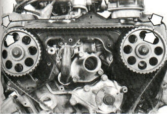

 Turn
tensioner with an Allen wrench to vary timing belt tension.
Turn
tensioner with an Allen wrench to vary timing belt tension.

 Align
number one on the distributor
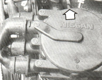
Align
number one on the distributorby turning rotor button towards the
arrow in the picture, not by where
the spark plug wire plugs in.
Automotive Torque Specifications |
||
| Home | Nissan | Nissan Maxima 1985-91 |
Nissan Maxima 1985-91
Engine
| 181 cu in (2960 cc) V6 | |||
|---|---|---|---|
| Component | Torque | ||
| air intake collector bolts | 13-16 ft. lbs. | ||
| block drain cock/Plug | 16-20 ft. lbs. | ||
| camshaft retaining bolt | 58-65 ft. lbs. | ||
| camshaft sprocket bolt | 58-65 ft. lbs. | ||
| crankshaft pulley bolt | 90-98 ft. lbs. | ||
| cylinder head bolts | step 1 | 22 ft. lbs. | |
| step 2 | 43 ft. lbs. | ||
| step 3 | NOTE | ||
| step 4 | 22 ft. lbs. | ||
| step 5 | 40-47 ft. lbs. | ||
| cylinder head temperature sensor | 9-12 ft. lbs. | ||
| exhaust gas sensor | 30-37 ft. lbs. | ||
| exhaust manifold nuts | 13-16 ft. lbs. | ||
| flywheel/Driveplate
mounting bolts (Apply thread locking compound prior to installation) |
72-80 ft. lbs. | ||
| intake manifold | bolts | 12-14 ft. lbs. | |
| nuts | 17-20 ft. lbs. | ||
| main bearing cap bolts | 67-74 ft. lbs. | ||
| oil pan drain plug | 22-29 ft. lbs. | ||
| oil pan mounting bolts | 61-70 in. lbs. | ||
| oil pick-up tube-to-Pump bolts | 12-15 ft. lbs. | ||
| oil pick-up tube bracket bolts | 36-78 in. lbs. | ||
| oil pump mounting bolts | 6 mm | 52-61 in. lbs. | |
| 8 mm | 108-144 in. lbs. | ||
| oil pump regulator cap | 29-36 ft. lbs. | ||
| rear main seal retainer bolts | 48-64 in. lbs. | ||
| rocker arm cover screws | 8.4-26.4 in. lbs. | ||
| rocker arm shaft bolts | 13-16 ft. lbs. | ||
| rod bearing cap nuts | 1985-87 | 33-40 ft. lbs. | |
| 1988 and up | step 1 | 10-12 ft. lbs. | |
| step 2 | 28-33 ft. lbs. | ||
| spark plugs | 14-22 ft. lbs. | ||
| thermostat housing cover bolts | 12-15 ft. lbs. | ||
| throttle chamber bolts | 13-16 ft. lbs. | ||
| timing belt Tensioner locking nut | 32-43 ft. lbs. | ||
| water pump-to-Engine block mounting bolts | 16-21 ft. lbs. | ||
| NOTE | Loosen all bolts. |
|
|
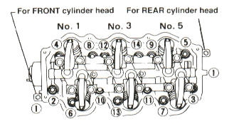
| Fig. 1 | Cylinder head bolt torque sequence |
|
|
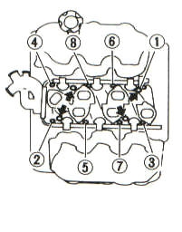
| Fig. 2 | Cylinder head bolt loosening sequence |
|
|
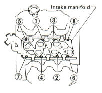
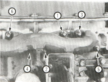
| Fig. 3 | Intake manifold torque sequence |
|
|
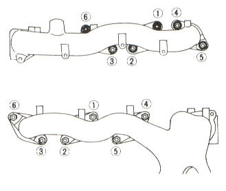
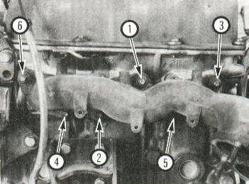
| Fig. 4 | Intake manifold loosening sequence |
|
|
| Fig. 5 | Exhaust manifold torque sequence |
|
|
| Fig. 6 | Rear exhaust manifold loosening sequence |
|
|
| Fig. 7 | Front exhaust manifold loosening sequence |
|
|
| Fig. 8 | Camshaft timing mark alignment |
|
|
| Fig. 9 | Crankshaft timing mark alignment |
| Turn
tensioner with an Allen wrench to vary timing belt tension. |
|
| Fig. 10 | Timing belt tension adjustment |
|
|
| Fig. 11 | Main bearing cap torque sequence |
|
|
| Fig. 12 | Cylinder location and firing order |
| Align
number one on the distributor by turning rotor button towards the arrow in the picture, not by where the spark plug wire plugs in. |
|
| Fig.13 | Distributor |
![]()
For images, go to www.torquespecs.com
|
|